Request a Quote

DALI Touch Panel Technology

How DALI touch panels switch, dim and colour-tune LED lighting over the two-wire DALI bus, by address, group or broadcast.

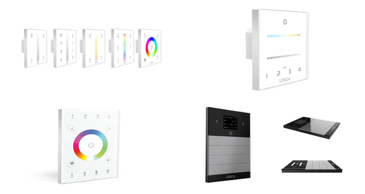
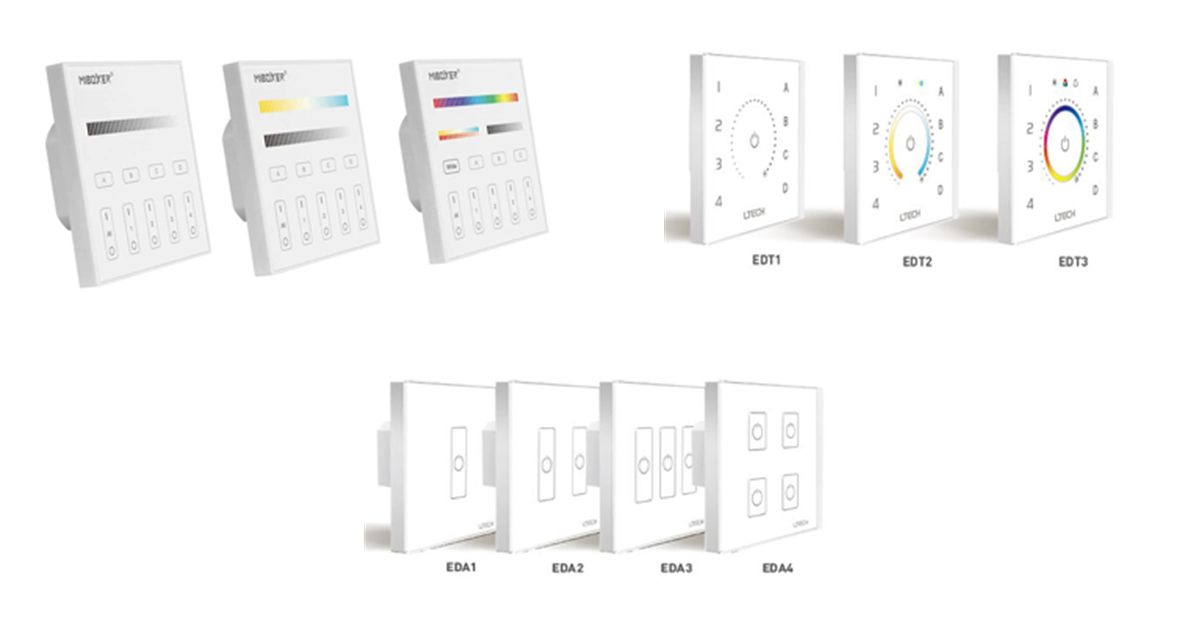
DP, EDT and EDA DALI touch panels

Overview

What are DALI touch panels?

DALI touch panels are glass wall controls that connect to the DALI bus, the two-wire control line that links DALI LED drivers. They do not switch the LED power themselves. Instead they send digital commands to the drivers, which then switch, dim and colour-tune the lights.

Each panel is powered from the bus, so only the two DALI wires run to the wall box. The panel can control drivers by individual address, by group or by broadcast, and its scene keys recall lighting scenes stored in the drivers. The panels follow the DALI standard, IEC 62386, so they work with DALI drivers of the matching device type.

  • Glass touch panel for a standard 86mm wall box
  • Powered from the DALI bus, with no separate supply
  • Unicast, group and broadcast control
  • Dimming (DT6) and colour control (DT8)
  • Scene keys that recall stored DALI scenes
DALI panels at a glance

  • Standard: IEC 62386
  • Power: DALI bus, under 6mA
  • Device types: DT6, DT8
  • Control: Dim, CT, RGB, RGBW
  • Zones: Up to 4 per panel
  • Addresses: 64 short, 16 groups
  • Size: 86 × 86mm
  • Ranges: DP, EDT, EDA
Request a Quote Technical Enquiry

The technology

How DALI panels work

A DALI bus power supply puts around 16V on the two bus wires. The panel and the drivers all connect to the same pair, which is polarity-free and can run alongside the mains cabling.

When a key or slider is touched, the panel sends a DALI command on the bus. Every driver hears it, but only the drivers with the matching short address or group respond, so one pair of wires can control many separate zones.

Scenes are stored in the drivers themselves. A short press on a scene key recalls the scene, and a long press saves the current light levels to it.

A DALI bus power supply feeds a two-wire DALI bus. A DALI touch panel and four DALI drivers connect to the bus, and the panel controls each driver's zone of lights by address or group. One pair of wires, many zones Mains in DALI bus PSU 16V DA1, DA2 Driver Zone 1 Driver Zone 2 Driver Zone 3 Driver Zone 4 DALI touch panel Commands to address or group On/off, dim, colour, scenes Panel powered from the bus
Simplified illustration: the panel and drivers share one two-wire DALI bus, and each zone key controls a driver address or group.

Device types

Matching the panel to the drivers

DALI groups drivers by device type. Choose a panel that sends the same type as your drivers.

Light typeDALI device typeDriver neededOur panels
Single colour dimmingDT6DALI dimmable CV or CC driverDP1S, EDT1, EDA1–EDA4
Tunable whiteDT8, TcDALI DT8 tunable white driverDP2S, EDT2
RGB colourDT8, x-yDALI DT8 colour driverDP3S, EDT3
RGBW / RGB+CCTDT8, RGBWAFDALI DT8 multi-channel driverDP3S

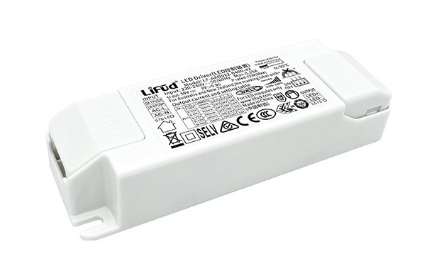
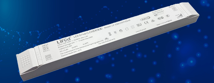
See also DALI LED driver technology and CV DALI LED driver technology.

Our range

DALI panels compared

Pick the light type, then how you want to set the address.

PanelControlKeysAddress setting
DP1SDimming (DT6)4 zones, 4 scenesDigital display and M key
DP2SCCT (DT8 Tc)4 zones, 4 scenesDigital display and M key
DP3SRGB, RGBW, RGB+CCT (DT8)4 zones, 3 scenesDigital display and M key
EDT1Dimming4 zones, 4 scenes, dimming ringRotary switches
EDT2CT (DT8 Tc)4 zones, 4 scenes, touch ringRotary switches
EDT3RGB (DT8 x-y)4 zones, 4 scenes, colour ringRotary switches
EDA1–EDA4On/off and dimming1 to 4 channel keysRotary switches

All panels are powered from the DALI bus and fit an 86mm wall box. The EDT and EDA panels measure 86 × 86 × 37mm.

Benefits

Advantages of DALI panels

Why a DALI wall panel suits commercial and larger lighting schemes.

Two wires only

Just the polarity-free DALI pair runs to the wall box, with no mains switching.

Bus powered

The panel draws its power from the DALI bus, so there are no batteries or adapters.

Flexible zoning

Control single addresses, groups or the whole bus, and rezone without rewiring.

Open standard

IEC 62386 commands work with DALI drivers of the matching device type.

Scenes

Recall up to 16 stored scenes, and save new ones with a long press.

Colour control

DT8 panels tune white light and colour as well as brightness.

Selection & set-up

Choosing and setting up a DALI panel

  • Match the device type: DT6 for dimming, DT8 for tunable white or colour, to suit the drivers.
  • Power the bus: fit a DALI bus power supply, for example 16V at 250mA, and wire DA1 and DA2 to the panel and drivers.
  • Address the drivers: give each driver a short address (0–63) or add it to a group (0–15).
  • Set the panel mode: choose unicast, group or broadcast and the start value. The four zone keys take that value and the next three.
  • Set the scenes: choose the first scene number. The scene keys take that scene and the ones that follow.
  • Fit the panel: fix the base to an 86mm wall box and clip the glass panel on.

Related technology and products

Complete the system with DALI drivers and controllers:

Ask an Engineer
64
Short addresses
16
Groups and scenes
2
Bus wires
86mm
Wall box size

Where DALI panels are used

Wherever lighting is controlled in zones from a DALI system.

Offices

Meeting room and open-plan zones, dimmed and tuned from the wall.

Hospitality

Hotel, restaurant and bar scenes recalled at the touch of a key.

Education

Classroom and lecture theatre presets for teaching and presenting.

Healthcare

Tunable white lighting for wards, clinics and treatment rooms.

Retail

Feature and colour lighting zones across the shop floor.

Residential

Whole-home DALI lighting with a wall panel in each room.

Explore

Explore DALI lighting control

Browse DALI drivers, controllers and panels.

FAQ

DALI panel questions

A DALI touch panel is a wall control that connects to the two-wire DALI bus instead of switching mains or LED power. It sends DALI commands to the drivers on the bus to switch, dim and colour-tune the lights, and it recalls scenes stored in the drivers. It fits a standard 86mm wall box.

No separate supply is needed at the panel. It is powered from the DALI bus itself, drawing less than 6mA. The bus does need a DALI bus power supply, such as a 16V, 250mA unit, which also powers the other control devices on the bus.

In unicast mode each zone key controls one driver short address (0 to 63). In group mode each zone key controls one DALI group (0 to 15), so many drivers respond together. In broadcast mode the panel controls every driver on the bus. The panel's four zone keys take four consecutive addresses or groups from the start value you set.

They are DALI device types defined in IEC 62386. DT6 is for single-channel LED dimming. DT8 is for colour control, using Tc for tunable white, x-y coordinates for RGB, or RGBWAF for multi-channel colour. The panel's control type must match the device type of the DALI drivers.

On the EDT and EDA panels, two rotary switches on the back select the mode and the start address: X sets unicast, group or broadcast and Y sets the value. On the DP panels, unlock the digital display with a long press of the M key, then step through the address, group and scene settings with the arrow keys.

Need help choosing a panel?

Our team can help you match DALI panels, drivers and power supplies for your project.

Talk to Our Engineers