Graphic COB LCD Technology
Monochrome Chip-on-Board graphic LCD modules from 2.2" to 5.67", with resolutions from 122x32 to 320x240. Find out how COB construction works, and how to choose a controller, interface and supply voltage.
Monochrome Chip-on-Board graphic LCD modules from 2.2" to 5.67", with resolutions from 122x32 to 320x240. Find out how COB construction works, and how to choose a controller, interface and supply voltage.
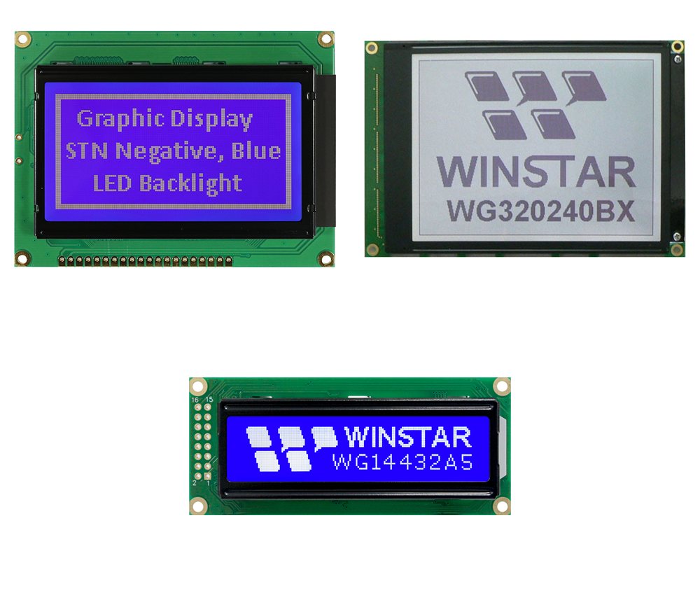
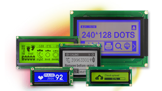
A graphic COB (Chip on Board) LCD is a monochrome dot matrix display mounted on its own printed circuit board. The controller and driver ICs sit on the back of the PCB under a protective epoxy, and the board also carries the connector pins and screw holes. The result is a rigid, ready to fit module that connects straight to your microcontroller, with no extra board to design.
As the authorised distributor for Winstar Display Corporation we offer graphic COB LCD modules from the 2.2" 122x32 WG12232A up to the 5.67" 320x240 WG320240BX, including the popular 128x64 WG12864A. Polariser options include reflective, transmissive and transflective, with LED backlights in yellow/green, white, blue, red, amber and RGB.
Controller mounted on a rigid PCB
Resolutions from 122x32 to 320x240
6800 and 8080 parallel interfaces
5V supply, with 3.3V options
Screw holes for secure mounting
Operating range -20℃ to +70℃
An LCD is a light valve. A thin layer of liquid crystal sits between two sheets of glass, with polarisers on the outside. Applying a voltage across a pixel twists the liquid crystal and changes how much light passes through, so the pixel appears dark or light against the background. An LED backlight lights the display in the dark.
In a COB module the glass panel and backlight sit on top of a PCB. The controller and driver chips are bonded straight onto the back of the board and sealed under black epoxy, then connected to the panel through conductive strips. The controller stores the image in its own memory and scans the display at a set duty cycle, for example 1/64 for a 128x64 panel, so your microcontroller only writes data when the picture changes.
Simplified illustration, not to scale: layer thicknesses are exaggerated for clarity
Why designers choose Chip on Board for robust, easy to fit graphic displays
Screw holes in the PCB let you fix the module securely in your product, with no brackets or extra boards.
The PCB supports the glass and protects the controller, suiting industrial equipment and control panels.
Header pins connect straight to your board or a ribbon cable. The WG320240BX has a 20-pin ZIF connector for flat cable.
LED backlights in yellow/green, white, blue, red, amber and RGB, with STN and FSTN panel types.
RA6963 models offer a character generator mode, and the ST7920 in the WG14432A supports Chinese fonts.
The WG12864A and WG320240BX are available with an optional touch panel.
Graphic COB LCDs run from 5V as standard. If your design runs from 3.3V, several models are available in a 3.3V version, usually with a negative voltage option that generates the LCD drive voltage on the module.
Some models have a negative voltage generator built in as standard, so no external LCD supply is needed.
| Supply | Example | Notes |
|---|---|---|
| 5V | WG12864A, WG16032E, WG128128A | Standard on all models |
| 3.3V | WG14432A3, WG12864AB | Internal booster or negative voltage |
| 3V or 3.3V option | WG12232A, WG160128B1 | Optional negative voltage version |
| Built-in negative voltage | WG16080D, WG320240BX | No external LCD supply needed |
COB graphic LCDs use an 8-bit parallel bus, in either the 6800 or the 8080 style. The two differ only in how the read and write control lines work, so check which one your controller and microcontroller expect. The WG14432A also offers an optional serial SPI interface.
Our engineers can help match a display, controller and interface to your design and arrange samples.
| Interface | Control Lines | Used On |
|---|---|---|
| 6800 parallel | E (enable) and R/W | WG12232A, WG14432A, WG16032E, WG12864A |
| 8080 parallel | Separate RD and WR | WG16080D, WG128128A, WG160128B1 |
| 6800 or 8080 | Selectable | WG320240BX |
| SPI (optional) | Serial clock and data | WG14432A |
Compare our graphic COB LCD modules by size, resolution, controller, interface and outline
| Model | Size | Resolution | Controller | Interface | Outline (mm) |
|---|---|---|---|---|---|
| WG12232A | 2.2" | 122x32 | AIP31520 | 6800 | 84.0 x 44.0 x 13.7 |
| WG14432A3/A5 | 2.44" | 144x32 | ST7920 | 6800, optional SPI | 85.0 x 36.0 x 13.2 |
| WG16032E | 2.87" | 160x32 | RW1020 | 6800 | 85.2 x 55.0 x 12.0 |
| WG12864A | 2.93" | 128x64 | NT7107, NT7108 | 6800 | 93.0 x 70.0 x 13.6 |
| WG16080D | 2.96" | 160x80 | RA6963 | 8080 | 93.0 x 70.0 x 13.6 |
| WG128128A | 3.06" | 128x128 | RA6963 | 8080 | 85.0 x 100.0 x 14.5 |
| WG160128B1 | 4.84" | 160x128 | RA6963 | 8080 | 129.0 x 102.0 x 16.5 |
| WG320240BX | 5.67" | 320x240 | S1D13700 | 6800, 8080 | 160.0 x 109.0 x 13.0 |
Outline thickness is the maximum, including backlight. See the datasheet or contact us for details. View Graphic COB LCD Modules →
Graphic COB LCDs suit equipment that needs a robust, easy to fit graphic display
Control panels, automation systems and machine status displays.
Test and measurement equipment, meters and data loggers.
Bench top medical devices with simple graphic user interfaces.
Boiler controls, HVAC panels and building management displays.
Point of sale terminals, vending machines and kiosks.
Inverters, chargers, UPS units and energy monitoring equipment.
Our engineering team can help specify or develop a custom solution for your exact requirements.
Talk to Our Engineers